LabJackU6
-
class
devices.LabJackU6(serialnum=None)[source] The class to represent the LabJack U6
- Parameters
serialnum (int) – The device serial number.
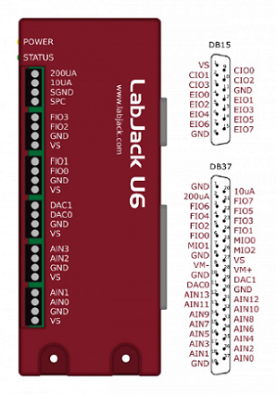
Ports that are made available with this class are:
Analog Output (0 to 5V) :
'DAC0','DAC1'Analog Input (+/-10V) :
'AIN0','AIN1', … ,'AIN13'Digital I/O :
'FIO0','FIO1', … ,'FIO7'Digital I/O :
'EIO0','EIO1', … ,'EIO7'
Device-specific methods:
get_bitdir - Gets digital port bit direction
set_range - Sets analog input voltage range
set_pwm_quad - Sets simultaneous PWM output and encoder input
Connect to the first found U6:
>>> from labjack_unified.devices import LabJackU6
>>> lju6 = LabJackU6()
>>> lju6.display_info()
>>> lju6.close()
You can also connect to a specific device using its serial number:
>>> lju6 = LabJackU6(360012345)
General
LabJackU6.get_labjacktemp(unit='C')[source]Get ambient temperature from LabJack’s internal sensor.
- Parameters
unit (str) – The temperature measurement unit. Valid values are
'C'or'F'. Default unit is'C'.- Returns
The internal sensor temperature reading.
- Return type
float
Get temperature reading in Celsius:
>>> lju6.get_labjacktemp()Get temperature reading in Fahrenheit:
>>> lju6.get_labjacktemp(unit='F')
I/O
LabJackU6.set_digital(name, state)[source]Write the digital state to an output port. It also sets the port direction to output.
- Parameters
name (str) – The port name to set the state.
state (int) – The digital state 0 = Low, 1 = High.
Set port
'FIO0'output to high and port'FIO1'to low:>>> lju6.set_digital('FIO0', 1) >>> lju6.set_digital('FIO1', 0)
LabJackU6.get_digital(name)[source]Read the digital state from an input port. It also sets the port direction to input.
- Parameters
name (str) – The port name to get the state.
- Returns
The state of the digital port. 0 = Low, 1 = High.
- Return type
int
Get port
'FIO2'input state:>>> lju6.get_digital('FIO2')
LabJackU6.get_bitdir(name)[source]Read the direction of the digital port.
- Parameters
name (str) – The port name to get the direction.
- Returns
The direction of the digital port. Input or Output.
- Return type
str
Get the direction of port
'FIO2':>>> lju6.get_bitdir('FIO2')
LabJackU6.set_analog(name, value)[source]Set analog output voltage.
- Parameters
name (str) – The port name to set the output voltage. Available ports are
'DAC0'and'DAC1'.value (float) – The output voltage between
0and5V.Set port
'DAC1'output voltage to2.2V:>>> lju6.set_analog('DAC1', 2.2)
LabJackU6.get_analog(name, mode='single-ended')[source]Get analog input voltage.
- Parameters
name (str) – The positive port name to get the voltage.
mode (str) –
Can be one of the two options:
'single-ended'(default value)
'differential'sets the ports to get a differential voltage.- Returns
The input voltage value.
- Return type
float
Get
'single-ended'voltage on port'AIN3':>>> lju6.get_analog('AIN3')Get
'differential'voltage betweens ports'AIN2'and'AIN3':>>> lju6.get_analog('AIN2', 'differential')Note
Differential reading uses two consecutive even-odd ports. Valid ports for differential reading are AIN0/2/4/6/8/10/12.
LabJackU6.set_range(names, ranges)[source]Set analog input voltage range.
- Parameters
names (str, list(str)) – The analog port(s) that will have their ranges modified. Use
'ALL'to set all analog input ports to the same range.ranges (float, list(float)) – The voltage range value to be used. Valid ranges are +/-
10,1,0.1,0.01V. If a single value is used, it will be applied to all ports in names.Set port
'AIN0'with a range of +/-1V:>>> lju6.set_range('AIN0', 1)Set port
'AIN0'and'AIN2'with a range of +/-0.1and0.01V:>>> lju6.set_range(['AIN0', 'AIN2'], [0.1, 0.01])Set all ports with a (default) range of +/-
10V:>>> lju6.set_range('ALL', 10)
Streaming
LabJackU6.set_stream(names, scanrate=50000, readrate=0.5)[source]Set and start data streaming.
- Parameters
name (str, list(str)) – The port name (or list of names) to be streamed.
scanrate (int) – The scan rate (Hz) of the data streaming. The default (and maximum) value is
50000Hz. The effective scan frequency of each port is the scan rate divided by the number of scanned ports.readrate (float) – The rate in seconds at which blocks of data are retrieved from the data buffer. The default value is
0.5seconds.Set data streaming on port
'AIN0'at25000Hz, every0.5s:>>> lju6.set_stream('AIN0', scanrate=25000, readrate=0.5)Set data streaming on ports
'AIN0'and'AIN1'at50000Hz, every1.0s:>>> lju6.set_stream(['AIN0', 'AIN1'], scanrate=50000, readrate=1.0)Note
Only analog input ports
'AIN0'to'AIN13'can be streamed. While it’s possible to stream digital ports, that hasn’t been implemented in this release.
LabJackU6.get_stream()[source]Get streaming data block.
- Returns
5-tuple
dt
The sampling period (s) between each data point.
data
The numpy m-by-n array containing the streamed data where m is the number of samples per port in the block and n is the number of ports defined in set_stream
numscans
The actual number of scans per port in the data block.
commbacklog
The communication backlog in % (increasing values indicate that the computer cannot keep up with the data download from the U6 driver)
devbacklog
The U6 device backlog in % (increasing values indicate that the device cannot keep up with the data streaming - usually not the case)
- Return type
(float, ndarray, int, float, float)
Retrieve scan period, data, and scan info:
>>> dt, datablock, numscans, commbacklog, U3backlog = lju6.get_stream()
PWM
LabJackU6.set_pwm(pwmnum=1, dirport1=None, dirport2=None, frequency=366)[source]Configure PWM output.
- Parameters
pwmnum (int) – The number of PWM output signals.
1or2PWMs can be used. For one PWM, the output port is'FIO0'. For two PWMs, the output ports are'FIO0'and'FIO1'.dirport1 (None, str) –
The type of ports that control the PWM direction for electric motor control. There are three options:
None- Default value (no direction ports are used)
'DAC'- Uses analog ports'DAC0'and'DAC1'
'DIO'- Uses digital ports'FIO2'and'FIO3'dirport2 (None, str) – Same as dirport1. It’s used when two PWM outputs are enabled. The
'DAC'option can only be used for one set of direction ports, unless the two motors are running synchronously. For the'DIO'option, digital ports'FIO4'and'FIO5'are used.frequency (int) – The PWM signal frequency in Hz. In the case of two PWMs, both will have the same frequency. Valid values are
183,366or732.Set 1 PWM for motor control on
'FIO0'with direction ports on'DAC0'and'DAC1'. The PWM frequency is the default366Hz:>>> lju6.set_pwm(dirport1='DAC')Set 2 PWMs on ports
'FIO0'and'FIO1'with a frequency of183Hz:>>> lju6.set_pwm(pwmnum=2, frequency=183)Set 2 PWMs for motor control on ports
'FIO0'and'FIO1', using the digital ports'FIO2'and'FIO3'for motor 1 direction, and'FIO4'and'FIO5'for motor 2 direction. The PWM frequency is732Hz:>>> lju6.set_pwm(pwmnum=2, dirport1='DIO', dirport2='DIO', frequency=732)Note
When using digital ports, a 10 kOhm resistor has to be connected from the LabJack VS port to each one of the DIO ports to ensure true high and low states.
LabJackU6.set_pwm_quad(dirport='DAC', zphase=False)[source]Configure 1 PWM output and 1 quadrature input. The PWM port is
'FIO2'and the phases A and B ports are respectively'FIO0'and'FIO1'.
- Parameters
dirport –
The type of ports that control the PWM direction for electric motor control. There are three options:
None- Default value (no direction ports are used)
'DAC'- Uses analog ports'DAC0'and'DAC1'
'DIO'- Uses digital ports'FIO4'and'FIO5'zphase (bool) – The logic value indicating if a Z phase reference pulse is used on port
'FIO3'.Set a PWM for motor control on
'FIO2'with direction ports on'DAC0'and'DAC1'. The encoder A and B ports are'FIO0'and'FIO1':>>> lju6.set_pwm_quad(dirport='DAC')Set a PWM for motor control on
'FIO2'with direction ports on'FIO4'and'FIO5'. The A-B-Z encoder A and B ports are'FIO0'and'FIO1'. The Z phase is on port'FIO3':>>> lju6.set_pwm_quad(dirport='DIO', zphase=True)Note
Due to limitations with internal clocks under this configuration, the PWM frequency is fixed at 732 Hz.
LabJackU6.set_dutycycle(value1=None, value2=None, brake1=False, brake2=False)[source]Set PWM duty cycle value.
- Parameters
value1 (float) – The PWM 1 duty cycle percent value between
-100and100.value2 (float) – The PWM 2 duty cycle percent value between
-100and100.brake1 (bool) – The motor 1 brake option used when dutycycle is zero. Brake is applied when
True. Motor is floating whenFalse.brake2 (bool) – The motor 2 brake option used when dutycycle is zero. Brake is applied when
True. Motor is floating whenFalse.Set duty cycle to
50% on PWM 1:>>> lju6.set_dutycycle(value1=50)Set duty cycle to
25% (reverse rotation) on PWM 2:>>> lju6.set_dutycycle(value2=-25)Set duty cycle to
20% and40% on PWMs 1 and 2:>>> lju6.set_dutycycle(value1=20, value2=40)Stop motor 2 and apply brake:
>>> lju6.set_dutycycle(value2=0, brake2=True)Note
Avoid suddenly switching the direction of rotation to avoid damaging the motor.
You can use the brake option True to hold the motor in position.
Note
If the method set_pwm_quad was used to configure both a PWM and a quadrature encoder, use only value1 and brake1 to control the motor output.
Quadrature
LabJackU6.set_quadrature(quadnum=1, zphase1=False, zphase2=False)[source]Configure quadrature encoder input.
- Parameters
quadnum (int) – The number of quadrature input signals.
1or2encoders can be used. For one encoder, the input ports are'FIO0'and'FIO1'. For two encoders, the input ports for the second one are'FIO2'and'FIO3'.zphase1 (bool) – The logic value indicating if a Z phase reference pulse is used for the first encoder. Port
'FIO2'is used if quadnum =1. Port'FIO4'is used if quadnum =2.zphase2 – The logic value indicating if a Z phase reference pulse is used for the second encoder. Port
'FIO4'is used for the first encoder and port'FIO5'is used for the second encoder. zphase2 is ignored if quadnum =1.Set ports
'FIO0'and'FIO1'for encoder with phase A and B signals only:>>> lju6.set_quadrature()Set ports
'FIO0'and'FIO1'for encoder phase A and B signals, and port'FIO2'for the reference Z phase:>>> lju6.set_quadrature(zphase1=True)Set 2 encoders with Z phase. A and B phases are on ports
'FIO0'and'FIO1'for encoder 1, and'FIO2'and'FIO3'for encoder 2. The Z phase ports are respectively'FIO4'and'FIO5':>>> lju6.set_quadrature(quadnum=2, zphase1=True, zphase2=True)
LabJackU6.get_counter()[source]Get current quadrature counter value.
- Returns
The counter value or a list with 2 values for 2 encoders.
- Return type
int, list(int)
>>> lju6.get_counter()Note
Because the qudrature counter counts rising and falling edges of phases A and B, a 1024 pulse/rev encoder will generate 4096 counts for a full shaft turn.
LabJackU6.reset_counter(counter1=True, counter2=True)[source]Reset quadrature counter value.
- Parameters
counter1 (bool) – The flag indicating whether to reset counter 1 or not. The default value is
Trueand it resets the counter.counter2 (bool) – The flag indicating whether to reset counter 2 or not. The default value is
Trueand it resets the counter.Resets current counter value of all encoders.
>>> lju6.reset_counter()Resets current counter value only for second encoder.
>>> lju6.reset_counter(counter1=False)Note
The count is only reset when a Z phase isn’t being used.
Note
If the method set_pwm_quad was used to configure both a PWM and a quadrature encoder, use counter2 =
'False'to reset the counter.